 Skip to content
Description
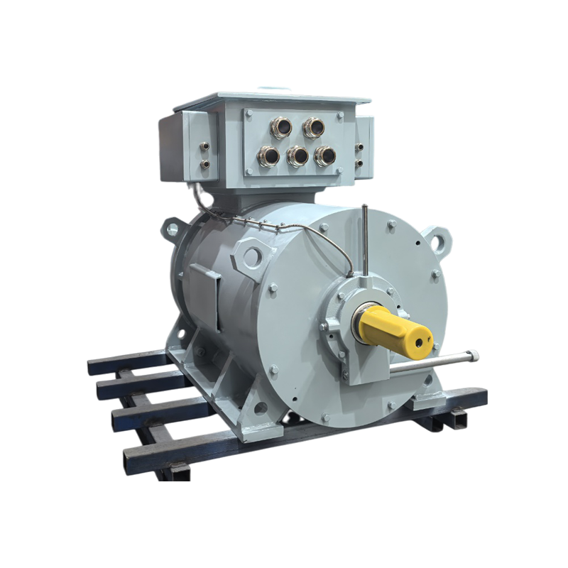
Medium-speed variable frequency permanent magnet synchronous propulsion motor
A revolutionary solution leading to efficient, reliable, and intelligent ship propulsion.
I. Product Strategic Positioning: Addressing Industry Pain Points
This series of permanent magnet synchronous propulsion motors (PMSMs) is specifically designed for shaft propulsion systems in single-propeller/multi-propeller vessels, aiming to systematically solve the core pain points in the current marine propulsion field through technological innovation:
| Industry pain points | Our Solution | Value created for customers |
|---|---|---|
| 1. Reliability anxiety | – No excitation system, no brushes/slip rings: Eliminates two major sources of failure. – Robust rotor structure: Built-in permanent magnets + high-strength sheath, adaptable to harsh sea conditions. – Simplified drivetrain: Medium-speed direct drive, eliminating the need for a reduction gearbox and its associated failure risks. | MTBF increased by more than 30%, unplanned downtime decreased by 50%, and operational reliability was significantly enhanced. |
| 2. High operating costs | – Ultra-high efficiency: Rated efficiency ≥97.5%, with even more significant efficiency advantages under partial load (3-8% higher than asynchronous motors). Low maintenance requirements: Essentially maintenance-free design, significantly reducing spare parts, lubricant, and labor costs. | Achieve a reduction of ≥20% in overall operating costs (fuel + maintenance), and shorten the investment payback period to 3-5 years. |
| 3. IMO Redundancy Requirements and Single-Paddle Risks | – Electrical redundancy design: The motor itself has high reliability, and combined with a dual-winding or dual-frequency converter power supply scheme, it meets the propulsion redundancy requirements of IMO MSC.1/Circ.1580 for single-propeller ships. | Provide compliant and efficient solutions for single-propeller vessel design, enhancing vessel safety. |
| 4. Single-engine, single-propeller energy efficiency bottleneck | – Wide efficiency range: Maintains high efficiency across the entire speed/torque range, optimizing the matching of ship navigation conditions. Power optimization: Flexibly adjusts the power output combination of the main engine and motors according to speed requirements. | It can improve the overall propulsion efficiency of single-engine, single-propeller ships by 5-15%, and is particularly suitable for mainstream ship types such as bulk carriers and tankers. |
| 5. Crew configuration pressure | – Condition monitoring and predictive maintenance: Integrates smart sensors and digital interfaces to enable remote health management. High degree of automation: Reduces daily inspection and maintenance workload. | Reduce reliance on senior marine engineers and optimize crew configuration to address the challenges of manpower shortages. |
| 6. Green transition and carbon pressure | – Direct Energy Consumption Reduction: Highly efficient direct reduction of fuel consumption and CO₂ emissions. – Compatible with Green Fuels: Adaptable to power generation systems driven by green fuel engines such as LNG, methanol, and ammonia. – Enables Hybrid Power Generation: Provides interfaces for future additions of batteries, fuel cells, etc. | Meet EEDI/EEXI and CII requirements, address EU carbon tariffs (CBAM), and enhance the green value of ship assets. |
| 7. Weak foundation of intelligent technology | – Native digitalization: With built-in core sensing and communication interfaces, it is an ideal execution terminal for ship energy management systems (PMS) and intelligent energy efficiency systems. | It provides key data support for ship lifecycle data management, energy efficiency optimization, and autonomous driving. |
II. Product Technical Specifications
1. Model and Power/Torque Coverage
This series adopts a modular and platform-based design, achieving full coverage from low-power auxiliary propulsion to high-power main propulsion.
| Application Level | Recommended frame size | Continuous rated power (kW) | Peak torque (kNm) | Typical speed (rpm) | Compatible propeller types |
|---|---|---|---|---|---|
| Assist/Side Push | 132 – 280 | 7.5 – 200 | 0.5 – 10 | 1000 – 3000 | Channel propeller, azimuth propeller |
| Small main push | H315 – H450 | 200 – 1500 | 10 – 70 | 500 – 1500 | Fixed-pitch propeller (FPP) and controllable-pitch propeller (CPP) |
| Medium-sized main recommendation | H500 – H710 | 1500 – 5000 | 70 – 250 | 200 – 1000 | Large CPPs for bulk carriers and tankers |
| Large-scale promotion | H800 – H1000 | 5000 – 10000+ | 250 – 350+ | 100 – 300 | CPP for ultra-large ships, direct drive replaces low-speed engines |
Note: “~350kNm” and “10000kW” are the upper limits of the current series, achievable using the H1000 frame, IC86W cooling, and a special magnetic circuit design.
2. Core Electrical and Mechanical Performance
2.1 Performance Parameters
Voltage Ratings (Un): 220V, 380V, 440V, 690V, 3300V, 6600V. 3300V/6600V is the mainstream and efficient choice for medium to high power propulsion.
Rated Torque (Tn): Precisely calculated based on power and speed. Overload Capacity:
Peak Torque: ≥ 2.2 times Tn, sustained for 60 seconds (meets DP-3 requirements and sudden load increases in severe sea conditions).
Overturning Torque: ≥ 2.5 times Tn, instantaneous (to handle extreme situations such as propeller jamming).
Efficiency Characteristics (η):
Rated Point Efficiency: ≥ 97.5% (Power > 500kW).
High-Efficiency Range: Efficiency ≥ 96% within the 25%-120% load range. Excellent efficiency remains at low speeds and high torque, a key advantage of direct-drive propulsion.
Power Factor (PF): Adjustable via inverter control, typically operating from 0.85 lead to 0.95 lag, improving grid quality.
Dynamic Response: Torque response time < 10ms, speed control accuracy ≤ 0.1%.
2.2 Permanent Magnet Rotor System (Core of Reliability)
Magnetic Circuit Topology: Built-in (IPM) V-type magnet arrangement. Advantages: High torque density, high saliency ratio, excellent field weakening and speed-enhancing capabilities, high mechanical strength.
Permanent Magnets: Utilizes high-temperature resistant, high-coercivity rare-earth permanent magnets (such as N48SH), operating at ≥150°C, and undergoes accelerated aging testing to ensure stable magnetic performance throughout its lifespan. Rotor Protection:
Carbon Fiber Composite Sheath: Utilizing prepreg winding and high-temperature curing processes, a high-strength, non-metallic sheath is formed, completely eliminating eddy current losses and resulting in lower permanent magnet temperature rise.
Real-time Rotor Temperature Monitoring: Embedded distributed fiber optic grating (FBG) temperature sensors or wireless passive temperature sensors monitor the temperature of each magnet in real time, achieving active demagnetization protection.
Shaft Design: Directly connected to the propeller shaft, the bearings must withstand significant propeller cantilever loads.
Special heavy-duty bearing design (e.g., double-row tapered roller bearings) is employed.
Standard shaft grounding device (advanced carbon brush + monitoring) effectively suppresses shaft current and protects the bearings.
3. Cooling System Configuration Strategy
Cooling method is crucial in determining power density, reliability, and noise.
3.1 Small to Medium Power Solutions (Recommended < 500kW)
IC411 (Self-ventilated): Optimal cost, suitable for small auxiliary propulsion systems in favorable environments.
IC416 (Forced Air Cooling): Provides stronger cooling through an independent fan, suitable for high-power applications or poorly ventilated environments. Air filtration is crucial to prevent salt spray corrosion.
3.2 Medium to High Power Solutions (Recommended > 500kW) – Essential for Main Propulsion
IC71W (Casing Water Cooling):
Principle: Integrated cooling water jacket within the casing.
Advantages: Compact structure, clean internal structure, high cooling efficiency, low noise.
Parameters: Cooling water (fresh water) inlet temperature ≤ 40°C, pressure 0.2-0.6MPa.
Application: The top choice for cost-effective 500kW – 3000kW propulsion motors.
IC81W (Air-Water Cooler):
Principle: Internal closed-loop air circulation, heat exchange through an air-water cooler.
Advantages: Combines internal cleanliness and efficient cooling, especially suitable for high-temperature, dusty environments in the engine room.
IC86W (Direct Water Cooling for Windings):
Principle: Direct water cooling of the stator hollow conductors.
Advantages: Peak cooling efficiency, highest power density, 20-30% reduction in size and weight compared to motors of the same power, and quietest operation.
Challenges: Requires a complex deionized water circulation system, resulting in high initial investment.
Applications: >3000kW ultra-high power vessels with stringent requirements for installation space and weight (e.g., luxury cruise ships, large roll-on/roll-off ships).
4. Installation Methods (IM Code) Explained: The propulsion motor installation method directly relates to bearing design, shaft alignment, and ease of maintenance.
IM B3 (Horizontal, Foot Mounted): Highly versatile, connected to the propeller shaft via a highly flexible coupling, isolating some vibration and misalignment. Requires a robust, independent base.
IM B5 (Horizontal, Flange Mounted): Compact structure, rigid connection, high transmission efficiency. Requires extremely high manufacturing and installation concentricity. Commonly used in integrated propulsion modules.
IM V1 (Vertical, Shaft Extension Downward): This is the typical installation method for most shaft-driven propulsion systems. The motor is located in the engine room, extending downward through the hull to connect with the propeller. The bearings need to be specially designed to withstand axial gravity and the weight of the propeller.
IM V10 (Vertical, Shaft Extension Downward, with Thrust Bearing): Based on V1, the motor integrates the main thrust bearing, directly bearing the forward and reverse thrust of the propeller. This simplifies the stern bearing arrangement but requires extremely reliable motor thrust bearings. It symbolizes high-end, integrated propulsion.
5. Insulation and Thermal Management
Insulation System (F/H Class): Utilizes inverter-specific insulation, tested at ≥2000V PDIV (Partial Discharge Initiation Voltage) to ensure long lifespan under PWM voltage. Class H insulation provides a higher temperature margin.
Thermal Management: Optimized design based on Computational Fluid Dynamics (CFD) and Finite Element Analysis (FEA) to ensure uniform and safe temperature rise of windings and permanent magnets under low-speed, high-torque conditions.
6. Protection Rating (IP)
IP54/IP55/IP56: Selected based on engine room location. For installations near the stern in humid environments, IP56 is the recommended standard, capable of withstanding strong water jets.
III. System-Level Solution Meeting IMO Redundancy Requirements
Providing solutions for single-propeller vessels that comply with IMO MSC.1/Circ.1580 (Redundancy Requirements for Propulsion and Steering of Electrical and Electronic Systems):
Motor Redundancy Design:
Dual Winding Design (Optional): Two independent three-phase windings are placed within the same stator core, each powered by an independent frequency converter. In the event of a failure in one winding, the other can operate at reduced power to ensure the vessel’s return to port.
Power Supply and Drive Redundancy: The motors are powered by two independent buses (e.g., main bus, emergency bus) or two independent frequency converters.
Equipped with an Automatic Bus Switching (ABT) device for seamless power switching.
Control System Redundancy: The propulsion control system (PCS) employs a dual-controller hot standby architecture.
The encoder feedback system uses dual encoders or encoders plus sensorless algorithm backup.


Reviews
There are no reviews yet.