 Skip to content
Description
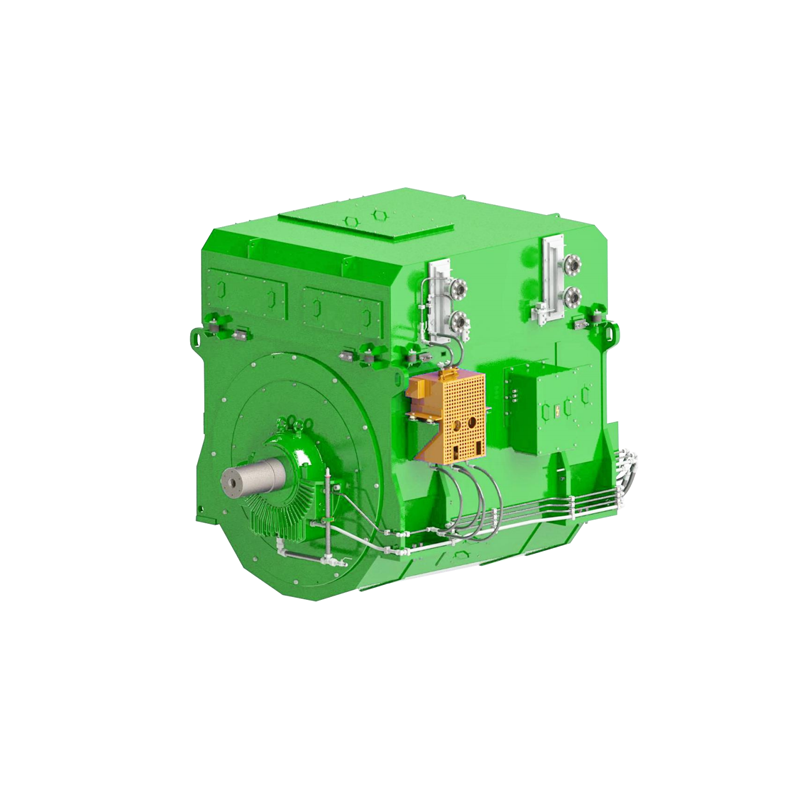
High-efficiency and stable core power source for marine power generation
Product Positioning and Core Value: This series of generators is designed specifically for the medium-speed power generation needs of modern marine power systems. It adopts mature and reliable electric excitation technology, combined with optimized structural design and high-quality manufacturing processes, to provide medium-speed power generation solutions for various types of ships with wide power coverage, stable operation, and convenient maintenance.
Detailed Technical Parameter Analysis
1. Model Specification System
| Application Classification | Frame size range | Power Coverage | Typical speed | Adapted scenarios |
|---|---|---|---|---|
| compact | H355-H450 | ~1500kVA | 1000-3000rpm | Auxiliary power stations, small vessels |
| Standard type | H500-H630 | 1500-4000kVA | 750-1500rpm | Merchant ship main generator, engineering vessel |
| medium | H710-H900 | 4000-7000kVA | 500-1000rpm | Large cargo ships and oil tankers |
| Large | H1000及以上 | 7000-10000kVA | 300-750rpm | VLCCs, ultra-large container ships, luxury cruise ships |
2. Detailed Explanation of Core Electrical Parameters
Power Characteristics:
Rated Capacity: ~10000kVA (Customizable)
Power Factor: 0.8 (Lag) Standard configuration, optional 0.9-1.0
Overload Capacity: 110% continuous operation, 150% overload for 60 seconds
Efficiency Curve: Maximum efficiency >97%, 75%-100% load efficiency >96%
Voltage System:
Voltage Rating: 220V/380V/440V/ 690V/3300V/6600V/11000V/13800V
Voltage Regulation: ±1% (AVR static accuracy)
Voltage Harmonics: THD < 2.5% (rated load)
Parallel Operation: Average Distribution Accuracy < ± 2.5%
Frequency Characteristics:
Rated Frequency: 50Hz/60Hz selectable
Transient Frequency Adjustment: ≤ ± 10% (sudden full load)
Recovery Time: < 3 seconds (to rated frequency ± 1%)
3. Mechanical Characteristics
Speed and Structure:
Speed Range: 300-3000 rpm (precisely matched to the prime mover)
Pole Configuration: 4-pole, 6-pole, 8-pole, 10-pole optional
Moment of Inertia: Optimized design to meet power grid surge requirements
Bearing System:
Drive End: Cylindrical roller bearings (axially free)
Non-Drive End: Deep groove ball bearings (axially positioned)
Lubrication Method: Grease/oil lubrication optional
Vibration and Noise Control:
Vibration Level: Complies with ISO10816-3 Class A standard
No-load Vibration: <1.8 mm/s (RMS value)
Full-load Vibration: <2.8 mm/s (RMS value)
Noise Level: ≤85 dB(A) @ 1m (depending on frame size)
4. Excitation System Technical Parameters
Excitation Method:
Brushless Excitation System (Standard Configuration)
Main Exciter: Permanent Magnet Auxiliary Exciter
Rotating Rectifier: Three-phase bridge type, IP54 protection
Voltage Setup: 100% rated voltage zero-start-up voltage
Automatic Voltage Regulator (AVR):
Regulation Accuracy: ±0.5% static, ±1% dynamic
Response Time: <0.1 seconds (90% step)
Protection Functions: Over-excitation/under-excitation limit, V/Hz limit
Communication Interface: Modbus RTU/TCP, CANopen
Excitation Characteristics:
Forced Excitation Capacity: 1.6 times rated excitation voltage, lasting 10 seconds
Peak Voltage: 2 times rated excitation voltage (instantaneous)
Demagnetization System: Optional demagnetizing resistor or demagnetizing switch
5. Protection Rating Configurations
IP54 Standard:
Dustproof: Dustproof, prevents harmful dust accumulation
Waterproof: Splash-proof, suitable for dry areas in the upper part of the engine room
Applicable Environment: General engine room, temperature 0-45°C
IP55 Enhanced:
Water Jet Resistance: Unaffected by low-pressure water jets from any direction
Corrosion Protection: Epoxy coating, salt spray resistance >500 hours
Applicable Environment: Lower and middle parts of the engine room, humid environments
IP56 Marine Rating:
High-Pressure Water Jet Resistance: Protection against strong sea waves
Sealing Design: Double sealing structure
Applicable Environment: Lower part of the engine room, harsh sea conditions
6. Installation Method Technical Specifications
B3 Foot Mounting:
Foot Dimensions: Standardized mounting hole layout
Mounting Surface: Flatness <0.1mm/m
Number of Feet: 4-8, depending on frame size
Applicable Power: Full power range
B5 Flange Mounting:
Flange Standard: ISO/SAE standard flange
Face Runout: <0.03mm
Coaxiality: <0.05mm
Applicable Scenarios: Compact spaces, integrated installation
7. Professional Cooling System Configuration
IC81W (Air-Water Cooling):
Cooling Method: Internal air circulation in the motor + external water cooler
Water Cooler: Shell and tube type, stainless steel
Cooling Water Flow Rate: 2-50 m³/h depending on power
Water Temperature Range: Inlet ≤32°C, temperature difference ≤10°C
Advantages:
High cooling efficiency
Clean motor interior
Strong environmental adaptability
Applicable Power: Optimal solution for the entire power range
IC86W (Closed-Loop Circulating Water Cooling):
System Composition: Internal water-cooled windings in the motor + external secondary heat exchange
Primary Cooling: Deionized water + antifreeze
Secondary Cooling: Central cooling water system
Technical Parameters:
Cooling Water Pressure: 0.2-0.5 MPa
Flow Rate Accuracy: ±5% control
Leakage Detection: Automatic alarm
Application Advantages:
Low noise (reduced by 5-8 dB)
Uniform heat dissipation
Suitable for high power density designs
Typical Applications: >3000kVA high-power units
8. Insulation and Temperature Rise Classes
H/F Class Insulation System:
Heat Resistance Class:
Stator Winding: 180°C (H Class)
Rotor Winding: 155°C (F Class)
Temperature Rise Limits:
Stator Winding: 125K (resistance method)
Rotor Winding: 105K (resistance method)
Core: 115K (thermocouple method)
Insulation Materials:
Mica Tape: Withstand Voltage >30kV/mm
Impregnated Varnish: Temperature Index ≥180℃
Slot Insulation: Three-layer Composite Structure
F/B Class Insulation System:
Heat Resistance Class:
Stator Winding: 155°C (F Class)
Rotor Winding: 130°C (B Class)
Temperature Rise Limits:
Stator Winding Rotor winding: 105K
Rotor winding: 85K
Economic advantages:
Manufacturing cost reduced by 8-12%
Suitable for normal operating conditions
Quality control and testing standards
Manufacturing process control
Raw material inspection: 100% traceability of key materials
Winding process:
Coil forming accuracy: ±0.2mm
Inter-turn withstand voltage: 2Un+1000V, 1 minute
Vacuum pressure impregnation (VPI):
Vacuum degree: <100Pa
Pressure: 0.4-0.6MPa
Curing: Staged temperature control
Dynamic balance test:
Accuracy class: G2.5 (ISO1940)
Test speed: 110% of rated speed


Reviews
There are no reviews yet.