

Description
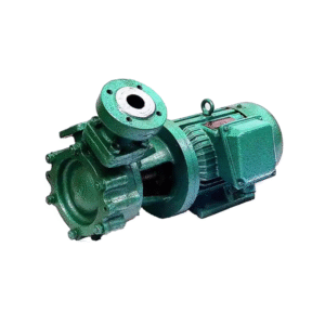
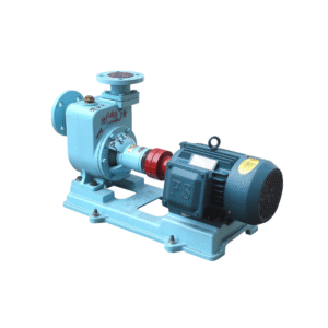
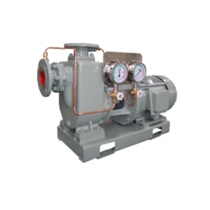
CLZ Series marine vertical self-priming centrifugal pump
一、 General
CLZ Series marine vertical self-priming centrifugal pumps are used at cabin bottom
to cool water and fight fire. It is able to carry sea water under 70 degrees.Fresh water and other non-eroding liquid.
Viewing from the motor end downward, this series pump rotates clockwise.
二、Main technical performance parameter
| Serial Number | model | 流量 m3/h |
扬程 m |
电机功率 Kw |
转速 r/min |
(NPSH)r m |
| 1 | 40CLZ—2(Z) | 5 | 60 | 2950 | 5.5 | 4.0 |
| 2 | 50CLZ—9(Z) | 27 | 14.5 | 2950 | 3 | 4.0 |
| 3 | 50CLZ—7(Z) | 12.5 | 20 | 2950 | 3.0 | 4.0 |
| 4 | 50CLZ—6(Z) | 21 | 30 | 2950 | 4.0 | 4.0 |
| 5 | 50CLZ—4(Z) | 12.5 | 32 | 2950 | 3.0 | 4.0 |
| 6 | 50CLZ—3(Z) | 12.5 | 50 | 2950 | 5.5 | 4.0 |
| 7 | 65CLZ—9(Z) | 25 | 20 | 2950 | 3.0 | 4.0 |
| 8 | 65CLZ—6(Z) | 25 | 32 | 2950 | 5.5 | 4.0 |
| 9 | 65CLZ—5(Z) | 25 | 45 | 2950 | 7.5 | 4.0 |
| 10 | 65CLZ—5.5(Z) | 30 | 35 | 2950 | 7.5 | 4.0 |
| 11 | 65CLZ—4.5(Z) | 25 | 60 | 2950 | 11 | 4.0 |
| 12 | 65CLZ—3(Z) | 25 | 80 | 2950 | 18.5 | 4.0 |
| 13 | 80CLZ—13(Z) | 45 | 21 | 2950 | 5.5 | 5.0 |
| 14 | 80CLZ—11(Z) | 50 | 25 | 2950 | 7.5 | 4.0 |
| 15 | 80CLZ—9(Z) | 50 | 32 | 2950 | 11 | 5.0 |
| 16 | 80CLZ-9 | 72 | 20 | 2950 | 15 | 5.0 |
| 17 | 80CLZ—9A | 60 | 25 | 2950 | 11 | 5.0 |
| 18 | 80CLZ—7.5 | 60 | 50 | 2950 | 18.5 | 4.5 |
| 19 | 80CLZ—7(Z) | 40 | 50 | 2950 | 15 | 4.0 |
| 20 | 80CLZ—6(Z) | 50 | 48 | 2950 | 15 | 5.0 |
| 21 | 80CLZ—6A | 30 | 60 | 2950 | 18.5 | 5.0 |
| 22 | 80CLZ—5.5 | 45 | 62 | 2950 | 18.5 | 4.5 |
| 23 | 80CLZ—5 | 50 | 67 | 2950 | 22 | 5.0 |
| 24 | 80CLZ—5A | 50 | 60 | 2950 | 18.5 | 4.0 |
| 25 | 80CLZ—4 | 50 | 80 | 2950 | 30 | 5.0 |
| 26 | 100CLZ-13 | 100 | 32 | 2950 | 18.5 | 5.0 |
| 27 | 100CLZ-18.5 | 100 | 20 | 2950 | 15 | 5.0 |
| 28 | 100CLZ-13A | 70 | 25 | 2950 | 11 | 5.0 |
| 29 | 100CLZ-12 | 80 | 32 | 2950 | 15 | 5.0 |
| 30 | 100CLZ-9 | 100 | 50 | 2950 | 37 | 5.0 |
| 31 | 100CLZ-9A | 110 | 36 | 2950 | 22 | 5.0 |
| 32 | 100CLZ-8 | 80 | 50 | 2950 | 22 | 4.8 |
| 33 | 100CLZ-7 | 80 | 60 | 2950 | 30 | 5.0 |
| 34 | 100CLZ-6 | 100 | 80 | 2950 | 45 | 5.0 |
| 35 | 100CLZ-5 | 100 | 120 | 2950 | 75 | 5.0 |
| 36 | 100CLZ-4 | 80 | 100 | 2950 | 45 | 5.2 |
| 37 | 125CLZ-23 | 160 | 20 | 2950 | 18.5 | 5.0 |
| 38 | 125CLZ-18 | 150 | 68 | 2950 | 55 | 5.0 |
| 39 | 125CLZ-16.5 | 160 | 32 | 2950 | 30 | 5.0 |
| 40 | 125CLZ-14 | 200 | 50 | 2950 | 55 | 6.0 |
| 41 | 125CLZ-13 | 250 | 30 | 2950 | 45 | 6.0 |
| 42 | 125CLZ-12 | 160 | 50 | 2950 | 45 | 6.0 |
| 43 | 125CLZ-9 | 200 | 80 | 2950 | 90 | 6.0 |
| 44 | 125CLZ-8 | 150 | 75 | 2950 | 75 | 6.0 |
| 45 | 125CLZ-7 | 200 | 125 | 2950 | 132 | 6.0 |
| 46 | 125CLZ-6 | 160 | 120 | 2950 | 110 | 6.0 |
| 47 | 125CLZ-5 | 120 | 120 | 2950 | 90 | 6.0 |
| 48 | 200CLZ-24.5 | 450 | 15 | 1450 | 37 | 5.5 |
How to select a marine vertical self-priming centrifugal pump
Step 1: Identify Core Needs and Applicable Scenarios
1. Typical Application Scenarios (Determine if they meet your needs)
Bulch Pumps: Pumping residual water from the bottom of engine rooms, cargo holds, etc., which may contain oil and air. This is the most classic application for vertical self-priming pumps.
Fire Pumps: As emergency fire pumps, they must be able to quickly self-prime and pump water from the sea or from tanks.
Ballast Pumps/Main Service Pumps: Used to adjust the ship’s buoyancy, requiring pumping water from various ballast tanks, resulting in complex operating conditions.
Sanitary Water Pumps/Sewage Treatment Systems: Discharging black water and grey water.
Diesel/Fuel Oil Transfer Pumps: Supplying fuel from low-level oil tanks to day tanks or main engine tanks.
2. Define Key Performance Parameters
Media: Is it seawater, fresh water, sewage, or oil? This determines the material selection.
Flow Rate and Head: Find your operating point on the performance curve. The flow rate and head of a self-priming pump will decrease during self-priming; confirm that the rated point meets the requirements.
Self-priming performance (core indicators):
* Self-priming height: Theoretically, it can reach 5-8 meters, but considering pipeline losses and efficiency, it is recommended to keep it within 4-5 meters.
* Self-priming time: Request the time required from the supplier to evacuate all air and reach the rated flow rate at the standard self-priming height. This is a key indicator of the pump’s self-priming capability, and is typically required to be within 2 minutes.
Step Two: In-depth Technology Selection (Key Decision Points)
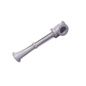
1. Self-priming Principle and Structure Confirmation: Vertical self-priming centrifugal pumps typically achieve self-priming using a “gas-liquid separation chamber” structure. Before initial startup, a certain amount of “priming liquid” needs to be pre-injected into the pump chamber. When the impeller rotates, it mixes the drawn-in air with the priming liquid. Due to centrifugal force in the separation chamber, gas and liquid separate; the gas is discharged, and the liquid flows back to participate in the circulation until all air is expelled, achieving normal pumping.
Selection Inquiry: Confirm which self-priming technology the supplier’s pump uses and inquire about its measured self-priming time and maximum self-priming height.
2. Material Selection (Corrosion Resistance and Durability)
Seawater/Oily Wastewater: 316L stainless steel is the first choice, offering excellent resistance to chloride corrosion. Bronze is also a traditional and reliable option.
Fuel Oil/Lubricating Oil: Cast steel or stainless steel can be used. Ensure the sealing material is compatible with the oil.
Domestic Sewage: Stainless steel is recommended, as it is easy to clean and corrosion-resistant.
3. Shaft Seal System (Reliability Lifeline) The shaft seal is the most vulnerable component to pump failure and has extremely high requirements in marine environments.
Mechanical Seal (Absolute Preferred):
Single-face mechanical seal: Suitable for most clean or slightly contaminated media, such as seawater and fresh water.
Double-face mechanical seal: With a separator fluid system, used for toxic, expensive, or absolutely leak-proof media (such as certain chemicals), offering the highest reliability.
Material: The friction pair must be resistant to media corrosion and abrasion. For seawater, silicon carbide to silicon carbide is the optimal combination.
Stuffing seal: Only found in older ship types or special applications. Due to the permissible slight leakage, it is not suitable for modern ship engine rooms and other locations where leakage is strictly prohibited, and is not recommended.
4. Motor and Drive
Marine Certified Motor: The motor must be certified by a classification society.
Protection Rating: At least IP55; for installation locations that may be subject to water erosion (such as the bilge), IP56 or IP66 is strongly recommended.
Insulation Class: Class F is standard, ensuring sufficient margin in high-temperature environments. Explosion-proof requirements: If used for conveying fuel or installed in hazardous areas, the motor must be explosion-proof (e.g., Ex d IIC T4).
Step 3: Compliance with Ship Codes and Installation Requirements
1. Classification Society Certification (Mandatory Threshold) The pump and motor, as a single unit, must obtain type approval from the target classification society. This is the bottom line for safety and quality and is indispensable.
Common classification societies: CCS (China), DNV (Norway), ABS (USA), LR (Lloyd’s Register), BV (France).
2. Installation and Piping Considerations
Installation Foundation: Vertical pumps require a sturdy, level foundation to ensure vertical installation.
Suction Piping: Piping should be as short and straight as possible, minimizing bends and valves to reduce self-priming resistance.
The suction pipe diameter must not be smaller than the pump inlet diameter.
Ensure all suction pipe connections are absolutely sealed; any leakage will cause self-priming failure.
Outlet Piping: It is recommended to install a check valve to prevent backflow of liquid during shutdown and shorten the next self-priming time.
Key Precautions (Warnings)
Priming is Required for Initial Start-up: Self-priming pumps are not “dry-start pumps.” Before initial operation, sufficient priming fluid must be added to the pump chamber through the priming port; otherwise, self-priming will fail and the mechanical seal will be damaged.
Prolonged Dry Operation is Strictly Prohibited: Even during self-priming, prolonged dry operation (exceeding the rated self-priming time) should be avoided, as this will rapidly lead to overheating and seal damage.
Regular Testing: For standby pumps such as fire pumps, self-priming functionality tests must be performed regularly to ensure immediate deployment in emergency situations.

Reviews
There are no reviews yet.