

Description
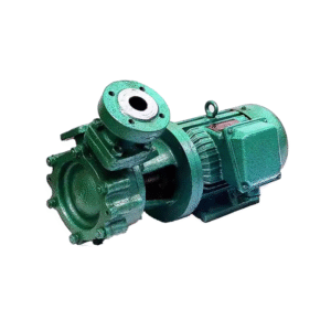
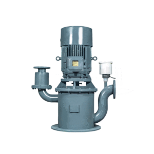
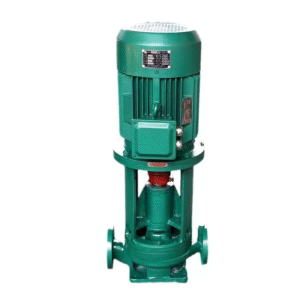
CLZ/2 Series marine vertical two stagcs self-priming centrfugal pump
一、General
CLZ/2 Series marire vertical two stages self-priming centrifugal pump is
compang’s abreast of the times production , It can be used tocooling. fire. Bilge and ballast and so. On, If apply to shipping and warship, The pumps trait is simple strultarc, small body and excellent self-prining cwithalt self-prining devive.
二、Main technical performance parameters
| model | 流 量 m3/h |
扬程 m |
转速 r/min |
电机功率 Kw |
必需汽蚀余量 m |
泵质量 kg |
| 125CLZ-5/2 | 51/51 | 30/65 | 1450 | 22 | 3.5 | 518 |
| 125CLZ-7/2 | 80/40 | 25/55 | 18.5 | 3.5 | 524 | |
| 125CLZ-9/2 | 116/58 | 24/61 | 22 | 4.1 | 548 | |
| 125CLZ-9/2A | 141/62 | 25.5/59 | 22 | 4.0 | 540 | |
| 125CLZ-9/2B | 112/54 | 15/52 | 18.5 | 4.1 | 526 | |
| 125CLZ-10/2 | 110/50 | 20/35 | 15 | 4.2 | 488 | |
| 150CLZ-6/2 | 95/95 | 36.5/86 | 55 | 4.9 | 806 | |
| 150CLZ-6/2A | 95/70 | 32/80 | 37 | 4.9 | 724 | |
| 150CLZ-17/2 | 149/95 | 27.5/77 | 45 | 5.1 | 778 | |
| 150CLZ-17/2A | 141/95 | 16.5/60.5 | 37 | 5.1 | 736 | |
| 150CLZ-15/2 | 199/182 | 33/79 | 90 | 5.0 | 1190 | |
| 150CLZ-12/2 | 199/99 | 23.5/70 | 45 | 5.1 | 772 | |
| 150CLZ-7/2 | 124/120 | 33.5/77 | 55 | 4.8 | 928 | |
| 150CLZ-7/2A | 215/120 | 23.5/65 | 45 | 4.9 | 840 | |
| 150CLZ-7/2B | 199/108 | 17/60.5 | 45 | 4.9 | 792 | |
| 200CLZ-13/2 | 257/124 | 24/68.5 | 55 | 4.3 | 936 | |
| 250CLZ-9/2 | 348/174 | 22/71.5 | 75 | 4.6 | 1080 | |
| 250CLZ-9/2A | 265/166 | 14.5/62 | 75 | 5.2 | 916 | |
| 250CLZ-19/2 | 389/182 | 22/70 | 75 | 5.4 | 1110 |
How to select a marine vertical self-priming two-stage centrifugal pump?
Step 1: Core Needs Analysis and Applicability Confirmation
1. Why is it needed? — Application Scenarios This type of pump should only be considered when your application simultaneously meets the following three conditions:
High Head Requirements: Pressure requirements that single-stage centrifugal pumps or vortex pumps cannot meet. A two-stage impeller in series can achieve more than double the head of a single pump.
Self-Priming Requirements: The pump is installed above the liquid level and needs to draw liquid from low-level tanks (such as the bottom of a ship or deep sea).
Space Constraints: Horizontal pumps occupy too much deck space; vertical structures save more space.
Typical Applications:
Main Fire Pumps / Emergency Fire Pumps: This is the most classic application. High-speed pumping of water from the sea is required, providing extremely high jet pressure. Vertical design saves engine room space, self-priming ensures immediate start-up, and two stages provide sufficient head.
High-Pressure Flushing Pumps: Used for high-pressure cleaning of decks and cargo holds.
Specific Ballast Pumps: Used in specific ballast systems requiring high head.
Boiler Feed Pumps: May be used if the boiler steam pressure requirement is very high.
2. Define Key Performance Parameters (Selection Basis)
Medium: Typically seawater or freshwater. The medium’s properties determine the material.
Flow Rate and Head: This is the fundamental reason for choosing a “two-stage” system. Accurately locate your operating point (Q, H) on the performance curve.
Self-priming Performance:
Self-priming Height: Maximum geometric suction head (typically 5-8 meters). For practical applications, pipeline losses and safety margins must be considered; it is recommended to keep it within 4-5 meters.
Self-priming Time: A core indicator. Obtain measured data from the supplier under standard operating conditions. For emergency equipment such as fire pumps, the time should be as short as possible (typically requiring self-priming and reaching rated operating conditions within 2 minutes).
Step Two: In-depth Technical Analysis and Selection Decision
1. Understanding the “Two-Stage” Structure and its Impact
Working Principle: Liquid passes sequentially through the first and second stage impellers. Each stage increases the head by approximately the same amount, resulting in a total head equal to the sum of the two stages.
Axial Force Balance: This is crucial for two-stage pump design. The two impellers are typically arranged “back-to-back,” causing the hydraulic axial forces to cancel each other out, significantly reducing the load on the thrust bearing and improving pump reliability and lifespan. When selecting a pump, it is essential to inquire about the supplier’s axial force balance solution.
Interstage Seal: The seal between the two stages is critical, preventing backflow of high-pressure stage liquid into the low-pressure stage, which would degrade efficiency and performance.
2. Self-Priming Function Implementation: Vertical self-priming two-stage pumps typically employ an “external gas-liquid separation chamber” or integrate the separation chamber above the pump body. Its self-priming principle is the same as that of a single-stage self-priming pump: it achieves self-priming through gas-liquid mixing, separation, and gas discharge. Due to its two-stage structure, the internal flow channels and separation chamber design are more complex.
3. Material Selection (Corrosion Resistance and Pressure Resistance)
Pump Casing and Impeller:
Seawater: 316L stainless steel is the standard and reliable choice. For large pumps or non-critical systems with strict cost controls, bronze can also be considered, but stainless steel is the mainstream.
Freshwater: Cast steel or stainless steel.
Shaft: Must be stainless steel to ensure strength and corrosion resistance.
Sealing Ring/Interstage Bushing: Usually made of materials with better wear resistance, such as stainless steel or special alloys.
4. Shaft Sealing System (Crucial) Two-stage pumps have higher outlet pressures, making the sealing requirements extremely stringent.
Mechanical Seal (Only Recommended):
Preferred: Double-face mechanical seal with Plan 53B flushing system.
Why? The high pressure of a two-stage pump will subject a single-face seal to enormous pressure, shortening its lifespan and increasing the risk. The Plan 53B system uses an external pressurized isolation fluid tank to supply a cleaner isolation fluid at a higher pressure than the pump chamber. This lubricates and cools the seals while absolutely preventing the pumped medium (such as seawater) from leaking into the engine room. Any leakage of the isolation fluid into the pump is harmless. This is the safest and most reliable configuration.
Sealing friction pair material: Must be extremely wear-resistant and corrosion-resistant. Silicon carbide-on-silicon carbide is the best choice for conveying abrasive media such as seawater.
5. Bearing System
Thrust bearing: Although the “back-to-back” impeller balances most of the axial force, a strong angular contact ball bearing or Kingsbury thrust bearing is still required to withstand the residual axial force and rotor weight. Its selection and life calculation are crucial.
Radial bearing: Deep groove ball bearing, used to support the rotor.
6. Motor and Drive
Marine certified motor: Power must be sufficient with appropriate margins.
Protection rating: Minimum IP56, IP66 recommended to withstand bilge flushing and harsh sea conditions.
Insulation class: Class F or higher.
Explosion-proof requirements: Determined based on the installation location.
Step 3: Ship Specifications and Installation Acceptance
1. Classification Society Certification (Mandatory) These pumps are often used in critical systems (such as firefighting), and their certification requirements are extremely stringent. Type approval from the target classification society (such as CCS, DNV, ABS, LR) is mandatory. Certification covers pump design, materials, and testing standards (such as performance, vibration, and noise).
2. Installation and Piping Requirements
Suction Piping: Must be absolutely sealed. Any minute leak will lead to self-priming failure or performance degradation.
Pipes should be short, straight, and thick, minimizing bends and valves to reduce resistance and improve NPSH.
A suitable filter screen should be installed at the suction inlet to prevent marine organisms and other foreign objects from clogging the two-stage impeller.
Outlet Piping: Check valves and isolation valves must be installed. Check valves prevent water hammer and backflow.
Foundation: A sturdy, level base is required to ensure the pump body is installed vertically and properly aligned.
3. Testing and Acceptance The supplier shall provide a complete test report, including at least the following:
Performance curve test: Verify that the flow rate, head, power, and efficiency meet the standards.
Self-priming test report: Record the self-priming time and maximum self-priming height.
NPSH (Net Positive Suction Head) test: Ensure the pump’s resistance to cavitation.
Vibration and noise test: Comply with classification society standards.

Reviews
There are no reviews yet.