
Description
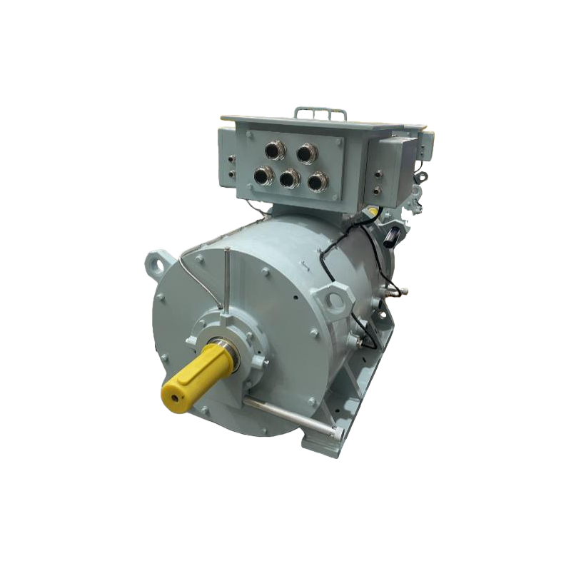
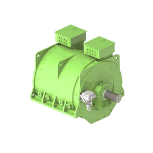
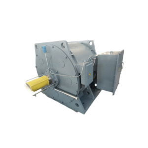
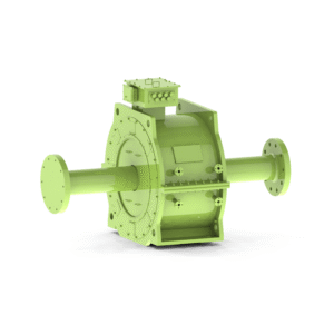
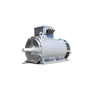
Medium-speed variable frequency permanent magnet synchronous generator
Core energy conversion hub of marine and offshore hybrid power systems
I. Product Strategic Positioning and Core Value
This series of permanent magnet synchronous generators is specifically designed for marine hybrid power and DC grid systems, serving as a key core device for realizing the three major functions of PTO (Power Take-Out), PTI (Power Take-In), and PTH (Power Take-Hybrid).
Core Value:
Core of Bidirectional Energy Flow: As an integrated motor/generator, it achieves efficient, flexible, and bidirectional conversion between diesel engine mechanical energy and marine grid electrical energy.
Efficiency Leap Engine: Permanent magnet technology delivers ultra-high efficiency of 96%-98%, combined with frequency converter control, achieving efficiency optimization across the entire operating range and significantly reducing fuel consumption.
Superior Dynamic Performance: Fast response speed and high torque density provide excellent maneuverability and grid support capabilities for ships.
Simplified System Architecture: Eliminating the excitation system results in a more compact and reliable structure, reducing maintenance points and facilitating a simpler and smarter marine energy management system (PMS).
II. In-depth analysis of application scenarios
| Application Mode | Function Description | Typical working conditions | Core requirements for motors |
|---|---|---|---|
| PTO | Diesel generator mode | The diesel engine drives the electric motor to operate as a generator and supply power to the power grid. | It generates electricity efficiently over a wide speed range and has excellent voltage regulation quality. |
| PTI | Electric propulsion mode | Powered by the grid, the motor drives the propeller. | High torque at low speeds, fast dynamic response, and four-quadrant operation. |
| PTH | diesel-electric hybrid propulsion mode | Simultaneous or alternating execution of PTO and PTI functions. For example, a single motor can both absorb power from a diesel engine to generate electricity (PTO) and absorb power from the grid to drive a propeller (PTI), thus achieving power coupling. | It features seamless switching between bidirectional operation and extremely strong torque/speed decoupling control capabilities. |
Compatible Platforms:
Engineering Vessels: Crane vessels, dredgers, pipelaying vessels, wind turbine installation vessels (requiring dynamic positioning (DP) and high load fluctuations).
Offshore Platforms: Drilling platforms, production platforms (requiring high reliability and low maintenance).
Hybrid Power Merchant Ships: Ro-Ro ships, ferries, research vessels, luxury cruise ships (emphasizing energy efficiency and comfort).
III. In-depth Technical Specifications and Parameter System
1. Model Specifications and Power-Speed Matrix
This series adopts a modular design based on torque density, decoupling power and speed, and achieving wide range coverage through adjustments to the magnetic circuit and cooling.
| Power density level | Corresponding frame number | Continuous rated power range (kVA) | Peak power/overload capacity | Optimal efficiency range |
|---|---|---|---|---|
| Standard type | H160 – H355 | ~ 50 – 1500 | 150% / 60秒 | 70%-110%Load, efficiency>96% |
| Enhanced | H400 – H560 | 1500 – 4000 | 180% / 30秒 | 60%-120%Load, efficiency>96.5% |
| High-density | H630 – H800 | 4000 – 10000+ | 200% / 10秒(instantaneous) | 50%-100%Load, efficiency>97% |
Note: “~10000kVA” is the current series upper limit, achievable with the H800 frame using IC86W cooling and H-class insulation. Customization for higher power is supported.
2. In-depth Electrical Performance Parameters
2.1 General Electrical Parameters
Rated Voltage (Un): Matches the DC bus voltage of the frequency converter. A full range of medium-voltage solutions from 690V to 13800V is available, with 3300V/6600V being the mainstream voltage levels for marine hybrid power systems.
Rated Speed (Nn): Can be arbitrarily specified within the range of 300-3000 rpm, directly matching the rated speed of the diesel engine or propulsion requirements, without the need for a gearbox.
Rated Frequency (fn): Controlled by the frequency converter, not the mains frequency. Wide motor design frequency range (e.g., 5-150Hz).
Power Factor (PF): Wide adjustable range, controlled by the frequency converter, typically operating arbitrarily within the range of 0.8 lead to 0.8 lag, providing reactive power support to the grid. Pole pairs (p): Optimized design based on rated speed and frequency, typically ranging from 10 poles (600 rpm @ 50 Hz) to 4 poles (1500 rpm @ 50 Hz), achieving optimal electromagnetic design.
2.2 Core Performance Indicators
Efficiency Map (η Map):
Maximum efficiency: ≥ 97.5% (high-density type, rated point).
Wide high-efficiency range: Efficiency not less than 96% within the 40%-120% load range.
Low losses: Permanent magnets have no excitation losses, and stray losses are minimized through optimized design.
Torque capability:
Continuous rated torque: Calculated based on rated power and speed.
Peak torque: ≥ 2.0 times rated torque, continuous for 60 seconds, meeting demanding conditions such as DP operation and sudden load increases.
Starting torque: Provides rated torque from zero speed.
Electrical time constant: Small, extremely fast dynamic response, torque response time < 5ms.
3. Mechanical and Structural Parameters
3.1 Permanent Magnet Rotor System (Core Technology)
Permanent Magnet Material: High coercivity, high temperature resistant neodymium iron boron (NdFeB) is used, such as 48SH (HcJ≥40 kOe, operating temperature≤150℃) or 42EH (HcJ≥35 kOe).
Magnetic Circuit Design:
Integrated Partial Motor (IPM) Rotor Structure: Permanent magnets are embedded inside the rotor core. Advantages: Higher torque density due to reluctance torque + permanent magnet torque; good mechanical strength, suitable for high speed; strong field weakening speed amplification capability.
V-shaped or Linear Arrangement: Optimizes the sinusoidal air gap magnetic flux density, reducing torque pulsation and iron loss.
Rotor Protection:
High-strength carbon fiber sheath or alloy steel sheath: Prevents permanent magnets from detaching under high-speed centrifugal force and provides damping.
Rotor Temperature Monitoring: Built-in fiber optic temperature sensor or PT100 directly monitors the permanent magnet temperature; an essential safety feature.
3.2 Bearings and Shaft Extensions
Bearing System: Reinforced design for four-quadrant operation and bearing propeller thrust (PTI mode).
Angular contact ball bearings or tapered roller bearings can be selected to withstand bidirectional axial forces.
Standard bearing insulation prevents shaft current corrosion.
Shaft Extensions:
B3 Mount: Standard cylindrical shaft extension with keyway.
B5 Mount: Can be directly connected to the prime mover; shaft extension with flange, transmitting high torque. Accurate calculation of torsional vibration is required.
4. Cooling System (IC Code) Configuration Strategy and Detailed Parameters
The choice of cooling solution is crucial to ensuring power density and reliability.
4.1 Small and Medium Power Solutions (≤ 500kVA)
IC411 – Self-Fan Cooling (TEFC):
Principle: Built-in shaft-mounted fan cools the external housing. Internal heat is conducted to the housing for dissipation.
Advantages: Simplest structure, no external dependence, low cost.
Disadvantages: Limited cooling effect, low power density.
Applications: Low-power auxiliary systems, clean environments.
IC416 – Forced Air Cooling (CACA):
Principle: An independent fan provides forced ventilation cooling to the motor. The airflow can be designed as a closed-loop circulation (dustproof) or open-loop.
Advantages: Significantly stronger cooling capacity than IC411, suitable for medium power and harsh environments.
Parameters: Airflow and air pressure are customized based on heat dissipation calculations; external air ducts are required.
4.2 Medium to High Power Solutions (> 500kVA, strongly recommended)
IC71W – Water Jacket Cooled:
Principle: A cooling water jacket is cast or welded inside the stator housing; cooling water flows directly through the jacket to remove heat.
System Composition: Motor + external cooling water circulation system (pump, valves, filters, heat exchanger).
Cooling Water Requirements: Fresh water or a fresh water/ethylene glycol mixture.
Inlet Water Temperature: Maximum 40°C.
Operating pressure: 0.2 – 0.6 MPa (casing side).
Flow rate: 10-100 m³/h, typically calculated based on heat dissipation.
Advantages: High cooling efficiency, compact structure, clean internal motor with no air wear loss, low noise.
Applications: Preferred solution for 500kVA – 3000kVA power range.
IC81W – With Air-Water Cooler (CACW):
Principle: Hot air inside the motor is cooled by a plate/shell-and-tube air-water cooler and then circulated. Closed-loop circulation within the motor.
Advantages: Combines the internal cleanliness advantages of IC71W with excellent cooling performance, suitable for engine room environments.
Parameters: Cooling water side requirements are similar to IC71W; air side requires a maintenance filter.
IC86W – Direct Water Cooled Winding:
Principle: The stator windings use hollow conductors; deionized cooling water flows directly inside the coils, resulting in the shortest heat dissipation path and highest efficiency.
System Composition: Motor + Deionized Water Circulation Unit (Circulation Pump, Deionizer, Expansion Tank, Conductivity Monitoring) + Secondary Heat Exchanger.
Requirements: Primary water must be high-purity deionized water with a conductivity < 0.5 μS/cm. This system is complex and has the highest cost.
Advantages: Maximum power density, minimized size and weight, and quietest operation.
Applications: High-power (>3000kVA) platforms with space and weight constraints.
5. Insulation System and Temperature Rise Management
5.1 Insulation System Characteristics
Stator Winding: Employs a dedicated insulation system driven by a frequency converter, capable of withstanding high-frequency du/dt and peak voltage.
Magnetic Wire: Corona-resistant enameled wire (e.g., IEC 60317-34).
Slot Insulation and Phase-to-Phase Insulation: High-temperature resistant, high-thermal-conductivity composite materials.
Impregnation Process: Vacuum pressure impregnation (VPI) using solvent-free epoxy resin with high thermal conductivity and high dielectric strength to ensure integrity and heat dissipation.
Insulation Life Prediction: Based on partial discharge (PD) testing and thermal aging models, ensuring long-life operation under variable frequency power supplies.
5.2 Temperature Rise Limits and Monitoring (Based on IEC 60034-1)
Stator Winding Temperature Rise (Resistance Method):
Class H: ≤ 125 K (Hot spot temperature ≤ 165°C at ambient temperature 40°C)
Class F: ≤ 105 K (Hot spot temperature ≤ 145°C)
Permanent Magnet Temperature Rise (Monitoring Point):
This is the most critical limiting parameter. Typically, the permanent magnet operating point temperature is required to be ≤ 120°C (for 120°C grade magnets), allowing sufficient margin to prevent irreversible demagnetization.
Monitored directly by rotor temperature sensors or estimated using thermal models.
Bearing Temperature: ≤ 95°C.
6. Protection Rating (IP) and Installation Method (IM)
IP54/IP55/IP56: Selection logic is the same as for electrically excited generators. IP56 is a common requirement in marine engineering.
B3 vs B5:
B3: More flexible, connected via coupling, facilitating installation alignment and vibration isolation. Requires an independent base.
B5: More compact structure, rigid connection, high transmission efficiency, often used in tightly coupled diesel engine-motor “one-to-one” units. Requires extremely high manufacturing and installation precision.
IV. Integration Interface with Variable Frequency Drive System (PCS)
This motor is part of a variable frequency drive system, and its design and selection must be coordinated with the frequency converter (AFE rectifier/inverter).
Voltage Matching: The relationship between the motor voltage and the inverter DC bus voltage is: Vdc ≈ √2 * Vll. Precise matching is required.
Encoder Feedback: Standard high-precision absolute multi-turn encoder (e.g., Heidenhain, Nikon) for precise positioning and speed feedback in Field-Oriented Control (FOC). Protection rating at least IP65.
Sensor Interfaces: Standard stator winding PT100 (per phase), bearing PT100, rotor temperature sensor (fiber optic/wireless). All signals are routed to a dedicated junction box.
Cooling Interfaces: Standard cooling water/air inlet/outlet flanges and interface dimension diagrams are provided.
Control Model Parameters: Precise d-q axis inductances (Ld, Lq), permanent magnet flux linkage (Ψf), stator resistance (Rs), and other parameters are provided for inverter controller parameter tuning.
V. Quality Control and Special Tests In addition to conventional motor tests, the following key tests for permanent magnet inverter motors are added:
Back-EMF Test: Verifies permanent magnet flux linkage and magnetic circuit symmetry.
Inductance Parameter Test: Measure Ld and Lq under different currents and rotor positions.
Demagnetization Risk Test: Test at the highest operating temperature and maximum demagnetizing current (e.g., short-circuit current) to verify no demagnetization of the permanent magnets.
Shaft Voltage/Shaft Current Test: Evaluate and develop suppression measures (e.g., insulated bearings, grounding carbon brushes).
Type Test under Inverter Power Supply: Test performance, losses, and temperature rise under actual operating conditions by co-firing with the matching inverter.
Four-Quadrant Operation Switching Test: Simulate rapid PTO/PTI switching to verify dynamic performance and control stability.
VI. Typical System Configuration Example
Example: Diesel-Electric Hybrid Power System of a 5000kW DP Engineering Vessel
Configuration: 4 diesel engines, each driving one H630-2500kVA permanent magnet synchronous generator (PTO mode).
Propulsion: 2 H710-3500kW permanent magnet synchronous motors (PTI mode) driving the propeller.
System: Networked via a 6600V DC bus.
Key parameters of the permanent magnet generator:
Frame size: H630
Cooling: IC81W
Protection: IP56
Insulation: H/F
Mounting: B5 (directly connected to diesel engine)
Function: High-efficiency PTO power generation, with PTI capability as backup shaft propulsion.
For customized technical solutions for this project, please provide a detailed system architecture diagram, diesel engine parameters, and operating condition requirements.

Reviews
There are no reviews yet.